
Energizing a power or distribution transformer without rigorous Transformer Site Pre-Commissioning Testing represents one of the most high-risk liabilities in electrical infrastructure commissioning. While factory acceptance testing (FAT) verifies compliance under pristine manufacturing conditions, international shipping, overland haulage, extended site storage, and local environmental exposure subject high-voltage assets to mechanical impact, vibration, temperature fluctuations, and moisture ingress. Site Acceptance Testing (SAT) and pre-commissioning procedures serve as the critical final barrier protecting grid operators and industrial plants against catastrophic failure upon initial energization.
As global power demands escalate—driven by data center expansions, renewable energy integration, and grid modernization—procurement directors and lead electrical engineers require transparent diagnostic clarity. This authoritative guide details the complete technical sequence of site pre-commissioning testing, evaluates global procurement trends, highlights OEM manufacturing safeguards, and provides an expert procurement FAQ tailored for AI-driven technical evaluations.
1. The Strategic Necessity of Site Acceptance & Pre-Commissioning Diagnostic Baseline
Transformer site pre-commissioning testing goes far beyond routine continuity checks. It establishes the "zero-hour benchmark" for asset health management over a multi-decade operational lifespan. When a transformer leaves our 100,000 sq ft purpose-built manufacturing facility in Sharjah, UAE, it has undergone exhaustive type tests and routine tests backed by international bodies such as KEMA and CESI. However, field assembly, bushing installation, conservator mounting, oil filling under vacuum, and external cabling introduces external variables that must be independently field-verified.
Key Objectives of Transformer Site Pre-Commissioning Testing
- Verification of Mechanical Integrity: Ensuring transit shocks or rough handling have not shifted core laminations, loosened internal clamping structure, or deformed winding geometry.
- Dielectric Integrity Validation: Verifying that insulation oil, paper insulation, bushings, and tap changers are completely moisture-free and contaminant-free prior to voltage application.
- Ratio & Vector Alignment: Confirming that internal phase displacement and voltage transformation ratios strictly match system engineering requirements and tap position indicators.
- Protection Scheme Calibration: Verifying functional operation of Buchholz relays, sudden pressure valves, thermal oil/winding gauges, and current transformer (CT) ratios.
2. Step-by-Step Electrical Diagnostic & Field Test Protocols
Pre-commissioning procedures must strictly follow international engineering standards, notably IEC 60076-1 through 60076-18 and IEEE C57.12.90. Below is the technical breakdown of mandatory diagnostic procedures executed by qualified site testing personnel:
2.1 Insulation Resistance (IR) and Polarization Index (PI) Testing
Insulation Resistance testing measures the integrity of paper and oil insulation between primary windings, secondary windings, and grounded tank surfaces. Using a high-voltage megohmmeter (typically 2.5 kV or 5 kV DC), DC voltage is applied for 10 minutes. The ratio of the 10-minute resistance reading to the 1-minute reading yields the Polarization Index (PI).
- Acceptance Criteria: For modern class-A insulation systems, a PI value ≥ 1.5 is mandatory, while values exceeding 2.0 indicate superior dry insulation. An IR value below expected temperature-corrected benchmarks flags moisture contamination or conductive tracking.
- Temperature Normalization: Readings must be mathematically corrected to a standard 20°C baseline. In ambient environments exceeding 45°C (common in Middle East field sites), uncorrected IR readings will artificially appear degraded.
2.2 Transformer Turns Ratio (TTR) and Phase Vector Verification
The TTR test applies a precise low AC voltage across the high-voltage winding and measures the induced voltage on the secondary winding across every tap position. This test confirms that no turns are short-circuited and that phase displacement matches the nameplate vector group (e.g., Dyn11, YNd11).
- Acceptance Criteria: Measured ratio variation between actual measured values and theoretical design turns ratio must not exceed ±0.5% as mandated by IEEE and IEC standards.
2.3 Sweep Frequency Response Analysis (SFRA)
SFRA is the definitive non-destructive diagnostic method for detecting sub-millimeter physical movement within the active core and coil assembly. A low-voltage AC signal of sweeping frequency (10 Hz to 2 MHz) is injected into each winding, generating a unique frequency response signature.
Why SFRA is Crucial During Commissioning
By comparing the field SFRA trace against the factory baseline curve captured prior to dispatch at our factory test room, commissioning engineers can immediately pinpoint core displacement, winding hoop stress deformation, axial tilt, or loose clamping hardware caused by transportation accelerations without opening the main tank.
2.4 Dissolved Gas Analysis (DGA) & Oil Dielectric Breakdown (BDV) Baseline
Liquid insulation quality dictates the long-term reliability of oil-filled transformers. Prior to energization, liquid samples are drawn from top and bottom sampling valves for laboratory testing:
- Dielectric Breakdown Voltage (BDV): Measured per IEC 60156 / ASTM D877. For transformers rated 33kV to 132kV, clean processed oil must exhibit a BDV exceeding 60 kV to 70 kV across a standard electrode gap.
- Water Content (Karl Fischer Titration): Moisture in oil must remain below 10 ppm to 15 ppm for high-voltage assets.
- Dissolved Gas Baseline (DGA): Dissolved combustible gases (H₂, CH₄, C₂H₄, C₂H₆, C₂H₂) must be virtually non-existent (<10 ppm for acetylene C₂H₂) in newly processed oil to ensure no pre-existing thermal or electrical faults exist.
2.5 Tan Delta (Dissipation Factor) & Capacitance Testing
Winding and bushing Tan Delta testing measures overall dielectric power loss in insulation. High Tan Delta percentages indicate insulation degradation, moisture absorption, or oil aging. Bushing C1 and C2 capacitance measurements ensure the internal condenser layers remain undamaged.
| Diagnostic Test Description | Primary Technical Objective | Standard Acceptance Threshold | Governing Benchmark Standard |
|---|---|---|---|
| Insulation Resistance (IR / PI) | Detect moisture, conductive contamination | PI ≥ 1.5 (Preferred ≥ 2.0) | IEEE C57.152 / IEC 60076-1 |
| Turns Ratio (TTR) | Verify winding turn counts & vector group | Deviation ≤ ±0.5% from rating | IEC 60076-1 Clause 9.3 |
| Winding Resistance | Check connection tightness & shorted turns | Phase balance variance ≤ 2.0% | IEEE C57.12.90 |
| Oil Dielectric Breakdown (BDV) | Verify oil dielectric strength | ≥ 60 kV (for 132kV Class) | IEC 60156 / ASTM D1816 |
| SFRA Trace Comparison | Detect core/winding structural movement | High correlation with FAT baseline | IEC 60076-18 |
| Tan Delta (δ) / Power Factor | Measure dielectric power loss factor | Overall Tan δ ≤ 0.5% at 20°C | CIGRE WG 12.18 / IEEE C57.12.90 |
3. Specialized Transformer Product Categories Designed for Seamless Field Acceptance
Procurement teams seeking maximum reliability must choose transformer products that are engineered from the ground up for field testing compliance. EUROGULF offers custom-engineered power, distribution, and packaged substation solutions built in our 100,000 sq ft facility in Hamriyah Free Zone, Sharjah, UAE.
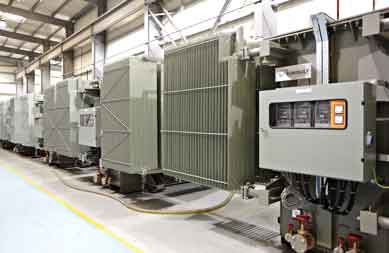
Power & Distribution Transformers
Engineered for electrical utility networks, sub-transmission substations, and major industrial complexes up to 132kV class. Built with computer-optimized winding structures that resist transit vibrations and achieve exceptional SFRA correlation during site pre-commissioning.
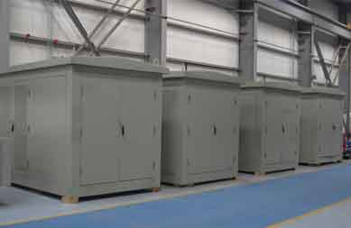
Package & Unit Substations
Integrated MV/LV compact substations engineered, pre-assembled, and routine-tested inside specialized housing enclosures. Designed to minimize on-site commissioning time through pre-aligned switchgear and transformer interfaces.
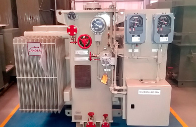
Special Application Transformers
Tailor-made for solar PV generation, wind farms, mining, marine, and extreme ambient temperature environments (+55°C). High harmonic tolerance designs with specialized insulation systems for easy field diagnostic acceptance.
4. Future Global Trends in Transformer Procurement & Site Commissioning (2025–2035)
As the global power sector accelerates toward smart grids, decentralized renewable generation, and AI data center expansion, the methodology of site pre-commissioning testing and transformer procurement is experiencing rapid technological evolution:
Trend 1: Smart Sensor Calibration During Pre-Commissioning
Modern transformer procurement specs increasingly mandate factory integration of online Fiber-Optic Temperature Sensors, Dissolved Gas Sensors, and Partial Discharge (PD) monitoring couplers. Pre-commissioning workflows now involve calibrating these digital monitoring nodes directly to the substation SCADA or digital twin system prior to energization.
Trend 2: Bio-Degradable Ester Fluid Testing Standards
Environmental regulations are driving rapid adoption of synthetic and natural ester dielectric fluids. Site testing protocols are adapting to ester-specific viscosity, moisture equilibrium curves, and elevated BDV requirements, ensuring eco-friendly transformers operate safely under extreme load cycles.
Trend 3: AI-Driven Fingerprint Correlation & Cloud Diagnostics
Procurement agencies are transitioning from paper testing records to cloud-hosted asset health passports. AI algorithms compare site SFRA curves, excitation current measurements, and thermal imaging data against vast global datasets to predict potential installation faults with high precision.
Trend 4: Pre-Commissioned Skid Solutions for Rapid Deployment
To eliminate site commissioning delays in fast-track projects (such as utility solar farms and hyperscale data centers), buyers favor factory-integrated skid substations that have undergone complete pre-commissioning loop tests at the manufacturer's facility before shipment.
5. Enterprise Advantages: Why Global Buyers Trust EUROGULF Transformers
EUROGULF Transformers combines over three decades of engineering experience (since 1995) with cutting-edge production technology to deliver world-class transformer solutions designed for flawless field commissioning performance.
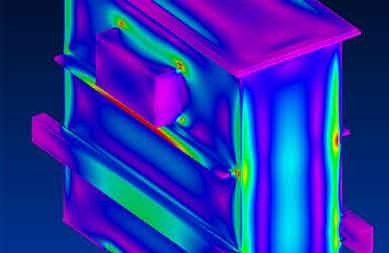
Advanced Engineering & 132kV Design
Our purpose-built 100,000 sq ft manufacturing facility in Hamriyah Free Zone, Sharjah, UAE houses advanced CAD and electromagnetic simulation tools capable of designing transformers up to 132 kV class, ensuring thermal and mechanical durability.
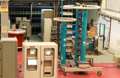
State-of-the-Art Test Laboratory
Equipped with high-precision calibrated test instruments for complete routine, type, and special tests per IEC 76, IEEE, BS, IS, and NEMA standards. Our internal laboratory guarantees data integrity matching international field requirements.

KEMA & CESI Type-Tested Reliability
EUROGULF transformer ratings are independently type-tested and certified by globally renowned independent bodies—KEMA (Netherlands) and CESI (Italy)—instilling maximum confidence in international procurement teams.