1. Executive Overview & Fundamental Electrical Dynamics of Sub-transmission Transformers
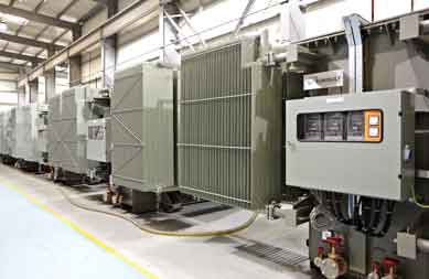
In modern electrical grid architecture, sub-transmission transformers fulfill the critical intermediary role between high-voltage bulk transmission lines (typically 220kV to 400kV) and localized medium-voltage distribution systems (typically 11kV to 33kV). Typically operating within the 33kV, 66kV, 110kV, 112kV, and 132kV primary voltage classes, sub-transmission transformers act as the core backbone for regional substations, large industrial complexes, municipal distribution hubs, and utility-scale renewable energy integration plants (Solar PV and Wind farms).
Unlike standard distribution units or ultra-high-voltage step-up transformers, sub-transmission assets must balance continuous duty cycles, unpredictable load variations, severe ambient temperature stress (particularly in desert or high-humidity tropical microclimates), and extreme mechanical short-circuit forces. The global transition toward decentralized renewable generation and smart grids has further complicated user intent for B2B buyers, requiring transformers that offer enhanced dynamic impulse withstand levels, lower total losses, and full compliance with low-carbon operational guidelines.
Engineering Gain: What Defines Sub-Transmission Class Integrity?
Sub-transmission transformers are engineered to handle high Basic Impulse Insulation Levels (BIL) up to 650 kV peak and dynamic short-circuit withstand currents exceeding 40 kA for 3 seconds. Achieving this requires specialized step-lap mitred core construction using High-Permeability Grain-Oriented (CGO/Hi-B) Silicon Steel, transposed copper conductors to eliminate eddy current losses, and custom-designed On-Load Tap Changers (OLTC) capable of maintaining output voltage stability within ±0.5% despite severe primary grid fluctuation.
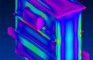
At EUROGULF Transformers, operating out of our state-of-the-art 100,000 sq ft purpose-built facility in Sharjah, UAE, sub-transmission designs undergo rigorous 3D finite-element electrostatic and thermal modeling. This ensures that electrical field stress inside the insulating paper-oil matrix remains strictly within safe breakdown limits, preventing premature aging and partial discharge (PD) failure.
2. High-Performance Sub-Transmission Transformer Product Recommendations
Based on extensive operational data across the Middle East, Africa, and global power utilities, EUROGULF recommends three specialized transformer series tailored to specific procurement and grid topologies.
Series ST-132/33 Heavy Utility Transformer
Engineered for primary sub-transmission grid step-down (132kV down to 33kV or 11kV). Ratings up to 90 MVA ONAN/ONAF/OFAF. Features high short-circuit force resistance, multi-stage OLTC, and fiber-optic winding temperature sensors.
Series ST-66/11 Industrial & Renewable Transformer
Optimized for 66kV/33kV/11kV substations, mining operations, and utility-scale solar parks. High over-excitation capability, low no-load losses, and custom dual-secondary winding options for harmonic suppression.
Series ST-33/11 Compact Substation Transformer
Designed for urban and industrial substations where physical footprint is restricted. Available in both conventional mineral oil and biodegradable synthetic ester fluids for enhanced fire safety and environmental protection.
Technical Specification Comparison & Engineering Matrix
The following technical matrix highlights the standard manufacturing boundaries and operational parameter guarantees offered across EUROGULF sub-transmission units:
| Technical Parameter |
Series ST-132/33 Utility |
Series ST-66/11 Renewable |
Series ST-33/11 Compact |
| Highest System Voltage (Um) |
145 kV |
72.5 kV |
36 kV |
| Rated Capacity Range |
10 MVA to 90 MVA |
5 MVA to 50 MVA |
2.5 MVA to 25 MVA |
| Primary / Secondary Voltage |
132kV / 33kV or 11kV |
66kV / 33kV or 11kV |
33kV / 11kV or 6.6kV |
| Vector Group Options |
YNdn11, YNyn0, Dyn11 |
Dyn11, YNd11, Dyn1 |
Dyn11, Dyn1, YNd11 |
| Cooling Configurations |
ONAN / ONAF / OFAF |
ONAN / ONAF |
ONAN / KNAN (Ester) |
| BIL Withstand (HV Winding) |
550 kV / 650 kV Peak |
325 kV / 350 kV Peak |
170 kV / 200 kV Peak |
| Short-Circuit Test Status |
KEMA / CESI Certified |
KEMA Type Tested |
CESI Type Tested |
| Tap Changing Equipment |
On-Load (OLTC) ±10% to ±15% |
OLTC or Off-Circuit (DETC) |
OLTC or Off-Circuit (DETC) |
Require Custom Sub-transmission Engineering Specifications?
Our design team calculates core flux densities, short-circuit forces, and thermal margins per project RFQ.
Inquire Now
3. Global Procurement Trends & Technological Evolution (2025–2035)
Global procurement directors and utility asset managers face unprecedented challenges driven by decarbonization mandates, aging grid infrastructure, supply chain delays, and stringent efficiency regulations (such as EU Ecodesign Tier 2 and US DOE efficiency standards). Procurement in AI-driven B2B landscapes requires evaluating transformers beyond initial purchase price, prioritizing long-term operational performance, material supply security, and sustainability.
Trend 1: Total Cost of Ownership (TCO) & Loss Capitalization Modeling
Modern procurement evaluation heavily weights Capitalized Loss Formula calculations over raw initial equipment cost. The Total Cost of Ownership (TCO) is determined by combining the capital expense ($CAPEX$) with the capitalized value of No-Load ($P_0$) and Load Losses ($P_k$):
TCO = Purchase Price + (A × No-Load Loss in kW) + (B × Load Loss in kW)
Where A-factor represents the cost of grid loss power evaluated over 25–30 years (often ranging between $6,000 to $12,000 per kW for continuous base load losses) and B-factor evaluates load-dependent losses based on projected load factors. EUROGULF’s design team uses low-loss amorphous and Hi-B silicon steel core stacking alongside optimized copper winding geometry to dramatically reduce $P_0$ and $P_k$, lowering the overall 30-year lifecycle cost by up to 22%.
Trend 2: Eco-Friendly Synthetic & Natural Ester Dielectric Fluids
Environmental regulations and urban safety guidelines are rapidly driving the substitution of traditional mineral oil with biodegradable natural and synthetic ester fluids (IEC 61039 / IEEE C57.147 compliant). Ester fluids offer:
- Superior Fire Safety: Fire point >300°C (Class K fluid rating), eliminating the need for expensive fire deluge systems and blast walls in dense substations.
- Environmental Protection: Readily biodegradable (>90% within 28 days per OECD 301), preventing soil and groundwater contamination in eco-sensitive zones.
- Extended Insulation Life: Ester fluids absorb moisture from paper insulation, slowing down paper cellulose hydrolysis and extending transformer life expectancy by up to 30%.
Trend 3: Smart Transformers with Integrated Asset Health Diagnostics
Artificial intelligence and predictive maintenance are changing substation monitoring. Modern sub-transmission transformers are delivered "Smart-Grid Ready," equipped with multi-gas Dissolved Gas Analysis (DGA) sensors, optical fiber winding temperature probes, online bushing monitoring, and real-time moisture-in-oil tracking via IEC 61850 protocol architecture. This capability allows utility operators to transition from reactive maintenance to condition-based automated asset health management.
4. EUROGULF Manufacturing Superiority & E-E-A-T Quality Rigor
Selecting a transformer manufacturer requires absolute confidence in engineering competence, material quality, and independent testing validation. EUROGULF Transformers brings over three decades of operational excellence to global procurement teams, backed by a world-class manufacturing infrastructure located in the Hamriyah Free Zone, Sharjah, UAE.
100,000 Sq Ft Purpose-Built Facility
Advanced manufacturing infrastructure equipped with clean-room coil winding stations, automated core-cutting lines, controlled vapor-phase drying plants, and heavy overhead crane capacity.
KEMA & CESI Independently Type Tested
Our transformer designs have been rigorously tested and certified by top international test laboratories—KEMA (Netherlands) and CESI (Italy)—confirming short-circuit and impulse withstand capabilities.
132kV Design Class Engineering
Utilizing high-end software simulation tools for electromagnetic field optimization, thermal fluid dynamics, and short-circuit mechanical stress calculations up to 132kV system rating.
Advanced HV Testing Laboratory
In-house high-voltage testing facility fully equipped to perform Routine, Type, and Special Tests (applied voltage, induced overvoltage, lightning impulse, partial discharge, and sound level measurement) per IEC 60076 & IEEE C57.
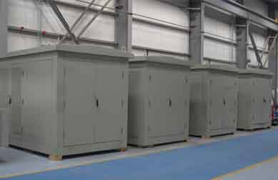
Below are original operational highlights showcasing EUROGULF’s design, high-voltage testing, and certified laboratory validation:
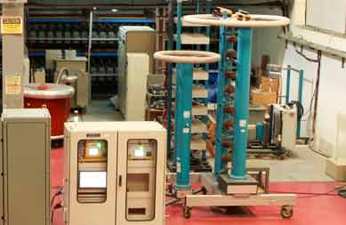
Precision High-Voltage Test Bay
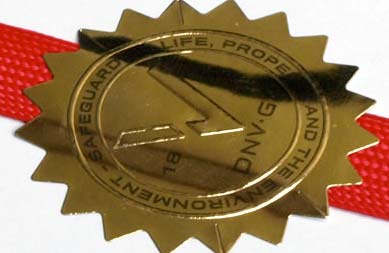
KEMA & CESI Certified Quality
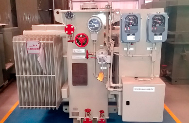
Custom Engineered Special Units
5. Global Procurement & Engineering FAQ (AI Search Intent Mining)
Below are detailed answers to top technical and commercial queries raised by utility engineers, EPC contractors, and procurement managers when sourcing sub-transmission transformers on AI platforms and search engine tools.
Q1: How do sub-transmission transformer losses impact the 25 to 30-year Total Cost of Ownership (TCO)?
Transformer losses consist of No-Load Losses ($P_0$) (core hysteresis and eddy currents present continuously whenever energized) and Load Losses ($P_k$) ($I^2R$ copper losses varying with load factor). Because transformers operate continuously over a 25–30 year lifecycle, the energy cost of losses frequently exceeds the initial purchase price by 1.5 to 3 times.
Using capitalized loss formulas, utility buyers assign monetary values to every kilowatt lost (e.g., $8,000/kW for $P_0$ and $2,500/kW for $P_k$). Purchasing a lower-first-cost transformer with higher losses will result in substantially higher lifetime operational expenditure. EUROGULF optimizes core geometry using step-lap mitred joints and high-grade silicon steel to achieve minimal core loss profiles that yield significant net savings over the unit's lifecycle.
Q2: What is the technical difference between ONAN, ONAF, and OFAF cooling for sub-transmission transformers?
ONAN (Oil Natural Air Natural): Cools oil naturally via convection through radiator banks and ambient air flow. Used for base load rating (100% capacity).
ONAF (Oil Natural Air Forced): Activates external cooling fans to increase airflow across radiators, boosting transformer cooling efficiency to handle peak loads (typically providing a 25% to 33% increase above base rating, e.g., 24 MVA ONAN / 30 MVA ONAF).
OFAF (Oil Forced Air Forced): Uses submerged oil pumps to forcefully circulate oil through heat exchangers alongside forced fan air. Designed for high-capacity sub-transmission units (40 MVA to 90 MVA) to control hot-spot temperatures during peak thermal stress.
Q3: Why are KEMA and CESI short-circuit type test reports critical for utility project approval?
When a short-circuit fault occurs near a sub-transmission substation, extreme mechanical forces (tens of metric tons of radial expansion and axial compression) are instantaneously exerted on the transformer windings. If the structural clamping system or conductor insulation is inadequately designed, the transformer will suffer catastrophic internal collapse.
KEMA (Netherlands) and CESI (Italy) are globally recognized independent test authorities. A successful short-circuit type test certificate proves that the physical transformer design withstands maximum calculated short-circuit current forces without structural or electrical degradation, satisfying utility compliance requirements worldwide.
Q4: How does synthetic ester fluid compare to conventional mineral oil in sub-transmission applications?
Synthetic ester fluids offer high thermal stability and a fire point above 300°C (Class K3), compared to ~145°C for mineral oil. This high fire safety rating allows sub-transmission substations to be built closer to residential buildings, industrial plants, or inside subterranean containment structures without requiring complex fire suppression systems.
Additionally, synthetic ester is readily biodegradable, reducing risk in environmentally sensitive locations such as coastal regions, water catchment zones, and solar parks. Ester fluids also retain moisture away from solid cellulose paper, preserving winding insulation strength over time.
Q5: What factory routine and type tests are performed on EUROGULF sub-transmission units before dispatch?
In compliance with IEC 60076-1 through 60076-5, every EUROGULF transformer undergoes 100% Factory Routine Testing prior to dispatch, including:
- Winding resistance measurement on all tap positions.
- Voltage ratio measurement and phase displacement vector group verification.
- Short-circuit impedance and load loss measurement.
- No-load loss and no-load current measurement.
- Separate-source AC withstand voltage test and Induced Overvoltage withstand test.
- Partial Discharge (PD) measurement (<10 pC target guarantee).
- Insulation resistance (Megger) and Dissipation Factor (Tan Delta) testing.
Type tests (Full lightning impulse voltage withstand, Temperature rise test) and Special tests (Sound level measurement, Frequency Response Analysis - SFRA) are routinely conducted upon client request.
Q6: How does EUROGULF handle custom voltage vectors and specialized tap changer requirements?
EUROGULF specializes in custom engineering. Our design engineers configure vector groups (such as YNdn11, Dyn11, YNyn0+d, or dual secondary outputs) to match existing grid phase rotation. For tap changers, we partner with top global OEM manufacturers (such as MR Reinhausen) to provide robust On-Load Tap Changers (OLTC) with automatic voltage regulators (AVR) or Off-Circuit Tap Changers (DETC) tailored to severe operating conditions.