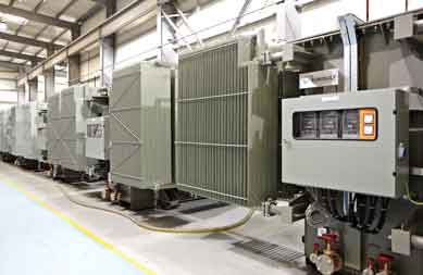
Pad-Mounted Compartmental Transformers
Tamper-proof, low-profile enclosure ideal for public areas without protective fencing. Features locked HV/LV cabinet doors, bay-o-net fuse protection, and current-limiting backup fuses.

An exhaustive technical manual and procurement resource for electrical utility directors, EPC contractors, and industrial consultants. Learn about structural topology, thermal dynamics, loss capitalization models, and IEC/IEEE compliance for medium-voltage ground mounted distribution systems.
Ground Mounted Distribution Transformers serve as critical node points in modern medium-voltage (MV) electrical distribution networks, stepping down distribution voltages (ranging typically from 11 kV, 22 kV, to 33 kV or 34.5 kV) to low-voltage (LV) levels (such as 400V, 415V, 480V, or 600V) for industrial complexes, commercial infrastructure, residential developments, and renewable power plants. Unlike overhead pole-mounted transformers, ground-mounted units are engineered to withstand significantly higher MVA load intensities, harsh mechanical stress, high short-circuit duty, and aggressive environmental exposure.
At EUROGULF Transformers, our ground-mounted designs incorporate high-grade Cold-Rolled Grain-Oriented (CRGO) silicon steel laminations with step-lap mitered core joints. This architectural configuration minimizes no-load eddy current losses, magnetic flux leakage, and operational acoustic emissions to align with strict urban noise abatement regulations. The primary and secondary winding assemblies utilize electrolytic-grade copper or high-conductivity aluminum strip conductors, insulated with high-density thermally upgraded kraft paper or advanced aramid insulation systems (e.g., Nomex) for high-temperature resilience.
Ground mounted transformers operating under continuous heavy loading in high ambient temperature regions (such as the Gulf Cooperation Council region experiencing ambient temperatures above 50°C) require rigorous thermal modeling. EUROGULF utilizes advanced finite element method (FEM) software to simulate oil convection currents, hot-spot temperature rise, and stray flux distribution to prevent premature insulation degradation and extend asset life beyond 30 years.
To address diverse global grid topologies, installation environments, and safety mandates, EUROGULF engineers and manufactures four primary categories of Ground Mounted Distribution Transformers. Each series is fully type-tested by internationally recognized laboratories such as KEMA (Netherlands) and CESI (Italy).
| Transformer Type | Rating Range (kVA) | Primary Voltage Class | Cooling Method | Key Application Environment | Standards Compliance |
|---|---|---|---|---|---|
| Pad-Mounted Compartmental (Single/Three Phase) | 50 kVA – 3150 kVA | Up to 36 kV | ONAN / KNAN | Underground distribution, urban residential, public parks, commercial complexes | IEEE C57.12.26, IEEE C57.12.34, IEC 60076 |
| Substation-Style Fluid-Filled Distribution | 500 kVA – 5000 kVA | Up to 36 kV | ONAN / ONAF | Industrial plants, oil & gas refineries, mining operations, heavy manufacturing | IEC 60076, BS EN 60076, NEMA ST-20 |
| Hermetically Sealed Corrugated Tank Units | 100 kVA – 2500 kVA | Up to 33 kV | ONAN / KNAN | Humid coastal regions, desert installations, zero-maintenance utility sub-grids | IEC 60076-1, EN 50588-1 (EcoDesign Tier 2) |
| Dry-Type Cast Resin Ground Mounted Units | 250 kVA – 4000 kVA | Up to 36 kV | AN / AF | High-rise buildings, indoor substations, hospitals, subways, data centers | IEC 60076-11, ANSI C57.12.01, F1/C2/E2 Class |
Tamper-proof, low-profile enclosure ideal for public areas without protective fencing. Features locked HV/LV cabinet doors, bay-o-net fuse protection, and current-limiting backup fuses.
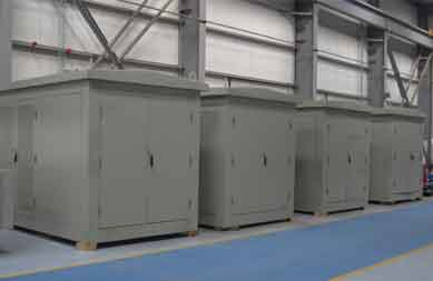
Engineered for direct flange or throat connection to Medium Voltage switchgear and Low Voltage switchboards. Supports high-duty industrial cycles and severe overload scenarios.
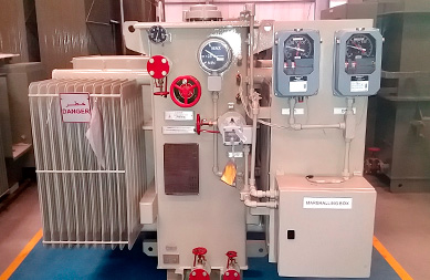
Tailored transformer solutions for Solar PV step-up (dual-winding low voltage), wind energy converters, K-factor rated variable speed drives, and railway traction substations.
Procurement strategies for Ground Mounted Distribution Transformers have shifted rapidly from evaluating initial purchase price (CapEx) to evaluating lifetime operating efficiency (OpEx). Power utility operators and commercial infrastructure investors now apply strict loss capitalization formulas during tender evaluations to minimize lifetime carbon footprint and energy expenditure.
When procuring ground-mounted distribution units, the true capitalized cost ($TCO$) over an operational lifespan of 25–30 years is calculated using the following industry-standard loss valuation equation:
Depending on regional utility policies, the capitalization factor A for no-load loss ranges between $5,000/kW to $12,000/kW (since core loss occurs continuously 8,760 hours per year), while B for load loss ranges between $1,500/kW to $4,500/kW. Selecting a high-efficiency EUROGULF Ground Mounted Distribution Transformer engineered with ultra-low loss CRGO steel or amorphous core alloys can result in net operational savings exceeding 40% of the transformer's original purchase price.
The global transition toward decentralized microgrids, high-penetration EV charging stations, and utility-scale solar/wind projects requires ground-mounted transformers to evolve from passive magnetic devices into intelligent, grid-interactive assets.
Modern ground-mounted units are increasingly equipped with integrated micro-sensors that feed real-time performance telemetry into utility SCADA systems via DNP3, IEC 61850, or Modbus protocols. Key monitored parameters include:
In distribution networks featuring low average load factors (such as solar farms during night hours or suburban residential circuits during mid-day), core loss accounts for the majority of wasted energy. Amorphous metal core transformers utilize a non-crystalline atomic structure that reduces core magnetic hysteresis losses by up to 70–75% compared to conventional CRGO steel.
Bi-directional power flow caused by rooftop solar generation leads to localized line voltage swelling and unbalance. EUROGULF is integrating compact, low-maintenance vacuum-interrupter OLTC mechanisms into ground mounted distribution transformers to enable automatic voltage regulation under load without creating electrical arcs in the oil tank.
Below are detailed engineering answers to the most frequent technical, operational, and procurement queries submitted by global power engineers and AI search query prompts regarding ground-mounted distribution units.
Standard transformer ratings according to IEC 60076 and IEEE C57.12.00 are calibrated for a maximum ambient temperature of 40°C and an average daily ambient of 30°C. In harsh desert regions like the Middle East, ambient temperatures frequently exceed 50°C with direct solar radiation. To prevent thermal breakdown of winding insulation:
The distinction lies in the primary high-voltage switching internal layout:
Short-circuit withstand capabilities are verified through dynamic mechanical and thermal stress testing according to IEC 60076-5 or IEEE C57.12.90. During testing at an independent laboratory like KEMA or CESI, the transformer secondary terminals are short-circuited while full rated symmetrical and asymmetrical short-circuit current is applied to the primary side for 2 to 3 seconds.
EUROGULF transformers utilize rigid core-clamp clamping structures, high-density pressboard spacers, and epoxy-diamond dotted paper (DDP) to ensure zero mechanical displacement or winding deformation under severe fault conditions.
While ester fluids incur a 15–25% higher initial fluid cost compared to standard mineral oil, they provide substantial operational lifetime advantages:
Dry-Type Cast Resin transformers are the benchmark choice for indoor substations in high-rise buildings, underground transit networks, and hospitals due to their complete absence of flammable liquid. They are certified self-extinguishing (F1 fire class) and produce zero toxic emissions. However, oil-immersed ground-mounted units provide superior outdoor weatherproofing (IP65 enclosure capability), smaller physical footprint per MVA rating, lower purchase price, and better natural heat dissipation in high-kVA applications.
BIL ratings define the transformer's ability to withstand transient lightning strikes and switching surges. Standard recommended BIL ratings for ground-mounted units include:
EUROGULF verifies BIL performance using impulse voltage generators in our internal high-voltage testing laboratory in accordance with IEC 60076-3.
Have specific technical questions for your upcoming grid tender?
Talk with a Transformer EngineerOperating from a purpose-built 100,000 sq ft state-of-the-art facility located in the Hamriyah Free Zone, Sharjah, UAE, EUROGULF Transformers brings over three decades of precision power engineering experience to global utilities, EPC contractors, and industrial developers across the Middle East, Africa, Europe, and Asia-Pacific.
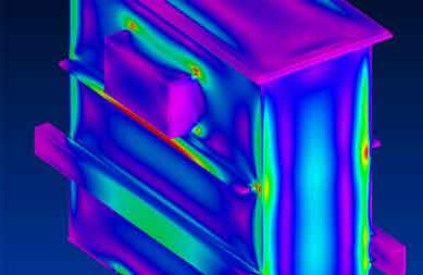
Equipped with sophisticated 3D finite element magnetic, thermal, and mechanical stress modeling software. Fully compliant with international standards including IEC, IEEE, BS, NEMA, and ANSI.
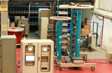
Our facility houses high-voltage testing instruments calibrated to perform routine, type, and special tests—including partial discharge measurement, full-wave lightning impulse withstand, and acoustic sound level testing.

EUROGULF transformer ratings are independently type-tested and certified by internationally renowned laboratories KEMA (Netherlands) and CESI (Italy), guaranteeing absolute quality, reliability, and short-circuit compliance.












Request detailed technical datasheets, CAD outline drawings, loss performance guarantees, and customized project quotations from our technical team.