01. Technical Foundation & Intent Analysis
Why Standard Transformers Fail Under Severe Duty Conditions
In modern industrial power distribution, renewable energy generation, and heavy manufacturing, standard power and distribution transformers frequently suffer premature breakdown, thermal runaway, or catastrophic insulation failure. Standard units designed in strict accordance with standard IEC 60076 or IEEE C57.12.00 assume pure sinusoidal voltage and current waveforms operating under continuous, stable linear loads. However, severe duty applications—such as multi-pulse static converters, electric arc furnaces (EAF), solar photovoltaic central inverters, phase-shifting drives, and traction sub-stations—subject transformers to extreme non-linear current harmonics, rapid thermal cycles, high mechanical vibration, and severe voltage transients.
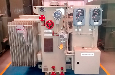
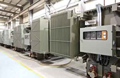
Special Application Transformers are purpose-built magnetic devices engineered from the physics level up to withstand these multidimensional stress vectors. Unlike off-the-shelf step-down distribution units, special transformers integrate customized core geometries, electrostatically shielded multi-winding topologies, enhanced mechanical clamping frameworks, elevated insulation thermal classes, and specialized dielectric fluids.
The Mechanics of Harmonic Loss and Thermal Stress
When non-linear loads draw current in discrete pulses rather than smooth sinusoids, they inject harmonic spectrums (typically the 5th, 7th, 11th, 13th, and higher order harmonics) back into the transformer windings. These harmonic currents drastically increase total losses through three distinct physical mechanisms:
- Eddy Current Losses in Winding Conductors ($P_{EC}$): Eddy current losses increase proportionally with the square of the current frequency ($f^2$) and the square of the conductor thickness. Unchecked, harmonic-induced eddy currents create localized thermal hot-spots inside inner winding layers, rapidly degrading cellulosic insulation paper.
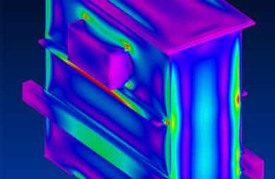
- Stray Load Losses in Structural Clamping & Tank Walls ($P_{OS}$): High-frequency leakage magnetic flux escapes the winding bundle and penetrates core clamping frames, structural tie-rods, and tank steel walls, inducing intense parasitic eddy currents and localized tank overheating.
- DC Bias Saturations: Solar inverter transformers and static converter circuits often introduce slight DC offset components. DC bias shifts the transformer’s magnetic operating point on the B-H hysteresis curve toward saturation, leading to massive magnetizing current spikes, elevated audible noise, and severe core loss amplification.
EUROGULF Transformers addresses these severe physical conditions using advanced finite element magnetic (FEM) simulation tools, continuously transposed conductors (CTC) to minimize skin effect, and specialized 3D thermal-fluid modeling to optimize cooling duct paths within custom-built core-coil assemblies.
Facing High Harmonic Failures or Custom Voltage Requirements?
Consult with EUROGULF senior transformer design engineers to simulate your load spectrum.
Send an Inquiry