
EUROGULF INSIGHTS & BLOG
Explore expert technical knowledge, engineering standards, industry trends, and innovations in power and distribution transformers.
TRANSFORMER TECHNOLOGY & GUIDES
In-depth analysis of transformer maintenance, high-voltage laboratory testing, and energy efficiency solutions.
INDUSTRY UPDATES & HIGHLIGHTS
Stay informed with technical perspectives, product developments, and energy grid innovations from our specialists.
What Are Sub Transmission Transformers?
Sub-transmission Transformers connect high-voltage transmission networks with the lower-voltage systems that supply local substations and distribution feeders. They reduce voltage to a level that downstream equipment can manage safely and efficiently. The exact voltage depends on the utility and region; there is no single worldwide threshold for sub-transmission. The boundary can feel fuzzy, and that matters when comparing equipment specifications.
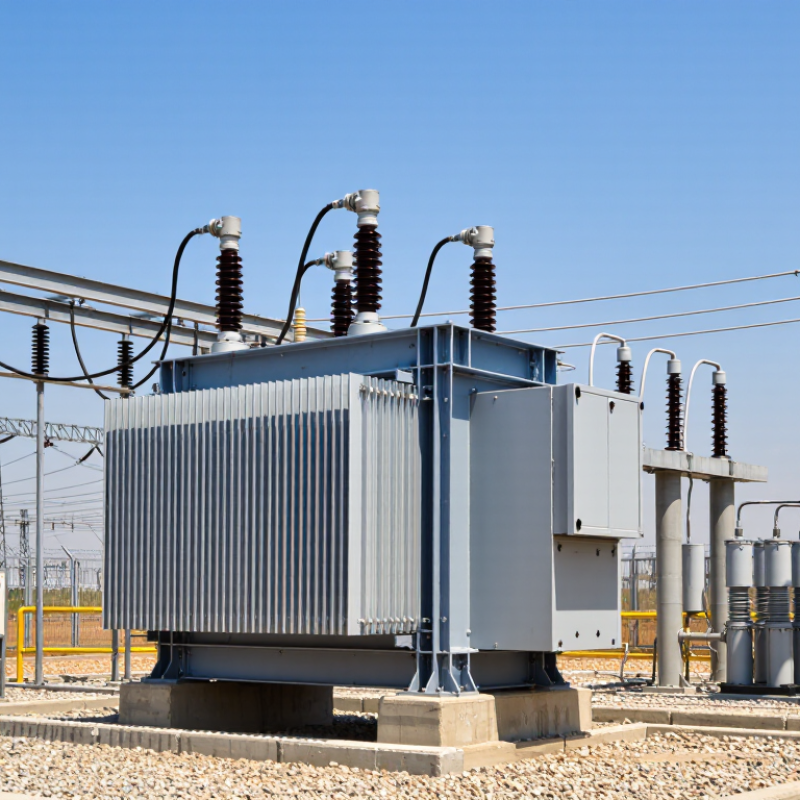
At a substation, a transformer may stand beside steel buswork, circuit breakers, and protection equipment. Its tank, bushings, cooling radiators, and tap changer each support reliable operation. Some units use liquid insulation, while designs and cooling methods vary. Short answer: they transfer power between network levels. Their rating, winding configuration, insulation system, and voltage-control features must match the grid’s operating conditions.
Understanding these transformers helps explain how bulk power reaches communities without sending transmission voltage directly into local distribution circuits. Engineers assess expected load, short-circuit levels, ambient conditions, and future demand before selecting a unit. Maintenance teams also monitor temperature, insulation condition, and oil quality where applicable. No single feature tells the whole story. A transformer that suits one substation may be unsuitable elsewhere. This guide clarifies what sub-transmission transformers do, where they fit in the power system, and which practical details shape their selection and operation.
Definition and Role of Sub-Transmission Transformers
Sub-transmission transformers connect high-voltage transmission networks to lower-voltage distribution systems. They are commonly installed at substations, where incoming power is stepped down for local networks. A typical sub-transmission voltage may range from about 33 to 138 kilovolts, but the boundary varies by utility and region. There is no single global definition. These transformers are not simply smaller transmission units: their capacity, voltage ratio, cooling, and protection must match the network they serve.
Their role is practical and essential. They reduce voltage to levels that feeder lines can carry toward neighborhoods, factories, and commercial sites. At a substation, operators may also use switching and protection equipment to isolate faults and redirect supply. The detail matters. A transformer near its capacity limit can restrict how much power reaches downstream feeders, even when upstream lines have room. The International Energy Agency reported that global electricity demand grew 4.3% in 2024, faster than its average growth over the previous decade. That trend makes careful capacity planning more important, though demand growth alone does not determine transformer needs. Local load patterns, redundancy plans, and equipment condition matter too. The boundary is not always tidy. Engineers must assess the actual network, not rely on a voltage label alone.
Where They Fit in the Power Grid
What Are Sub Transmission Transformers?
Where They Fit in the Power Grid
A sub-transmission transformer links the high-voltage transmission network with lower-voltage sub-transmission circuits. It usually sits at a transmission substation, where power arrives over large lines and leaves along routes serving towns, industrial areas, or groups of distribution substations. Its role is a change in voltage, not a direct connection to every home.
The exact voltage levels vary by region and utility. A transformer may lower incoming power to a level suited to sub-transmission lines, which carry electricity across shorter distances than major transmission corridors. From there, downstream substations reduce voltage again for local distribution. The boundary is not always neat; grid layouts reflect terrain, load growth, and decisions made over many years.
Look at a substation yard and the transformer is often the large, tank-shaped unit among steel structures, conductors, and protective equipment. Its cooling fans may start when demand rises. Relays and circuit breakers help isolate faults, while operators monitor loading and temperature. These details matter: a transformer can be powerful, but it is not a simple bottleneck that can be swapped without planning. Engineers must consider nearby lines, backup paths, and future demand. That is where diagrams can mislead. The grid is connected, but each site has its own constraints.
What Are Sub Transmission Transformers? - Where They Fit in the Power Grid
| Grid Element | Typical Voltage Level | What It Does | How a Sub-Transmission Transformer Fits | Illustrative Example |
|---|---|---|---|---|
| Bulk transmission network | Often 115–765 kV, depending on the grid | Carries large amounts of electricity over long distances from generating stations toward major load areas. | Receives power at a bulk supply substation and steps it down to a lower voltage for regional delivery. | 230 kV stepped down to 69 kV |
| Sub-transmission network | Commonly about 33–132 kV; terminology and voltage ranges vary by region | Moves power from bulk substations to local substations and large customers across a city or region. | Connects the higher-voltage transmission system to the sub-transmission system, or links sub-transmission voltage levels. | 115/69 kV transformer supplying a 69 kV network |
| Substation serving a distribution area | Sub-transmission input commonly around 33–132 kV; distribution output often 4–35 kV | Supplies primary distribution feeders, which carry electricity toward neighborhoods, businesses, and other customers. | Steps sub-transmission voltage down to the primary distribution voltage used by local feeders. | 69/13.8 kV or 33/11 kV transformer |
| Primary distribution feeder | Commonly about 4–35 kV | Distributes electricity from a local substation through communities and commercial or industrial areas. | Usually operates on the lower-voltage side of the sub-transmission transformer; it is not the transformer itself. | 13.8 kV feeder supplied by a substation transformer |
| Distribution transformer | Primary distribution voltage down to customer utilization voltage | Provides the final voltage reduction for homes and many businesses. | Typically sits farther downstream than a sub-transmission transformer, near customer loads. | 13.8 kV stepped down to 120/240 V or 400/230 V, depending on the system |
| Typical equipment rating | Voltage ratings are selected for the connected network | Transformer capacity is specified in megavolt-amperes (MVA), with thermal limits and operating conditions taken into account. | Sub-transmission units may range from several MVA to well over 100 MVA; the required rating depends on local demand, redundancy, and future growth. | A 40 MVA unit is one possible project-specific rating, not a universal standard |
| Common design and protection features | Chosen for the system voltage, fault level, and operating requirements | Supports safe switching, fault isolation, voltage control, and reliable power delivery. | May include on-load tap changing, cooling equipment, protective relays, bushings, and monitoring systems, depending on the design. | Tap changer adjusts the turns ratio to help regulate the secondary voltage under changing load |
| Why it matters | Bridges bulk supply and local distribution | Helps deliver electricity at voltages suited to regional networks and downstream equipment. | Its location and capacity affect voltage quality, network loading, and the ability to serve local demand. | Provides a key voltage transition between a regional supply network and a distribution substation |
Voltage classifications and equipment ratings differ among countries and utilities. The ranges and examples above are illustrative; actual system values are set by the local grid design.
How They Transfer and Regulate Electrical Power
Sub-transmission transformers connect high-voltage grid lines to lower-voltage networks that feed local substations and large customers. Their main task is to change voltage levels while transferring electrical power through electromagnetic induction. A transformer may reduce voltage for distribution, though some networks use different arrangements. The exact voltage depends on the utility system.
At a substation, thick conductors carry power into the transformer, where coils and a steel core transfer energy between circuits. Tap changers adjust the coil ratio to help keep the outgoing voltage within an operating range. Some can make adjustments while energized; others require the equipment to be taken offline. Small changes matter. Voltage can sag when demand rises or when a long line carries heavy current. The transformer can compensate within limits, but it cannot fix every problem on the grid. That part is easy to overlook. Operators also monitor load, temperature, and voltage readings, then coordinate settings with nearby equipment. On a rainy evening, for example, rising neighborhood demand may call for a different tap setting. The control is useful, not magical, and settings may need review as conditions change.
Key Components, Ratings, and Common Designs
A sub-transmission transformer transfers power between sub-transmission lines and a substation’s distribution-voltage network. Its core guides magnetic flux, while copper or aluminum windings change the voltage. Insulation separates energized parts, and the tank protects the active assembly. Bushings carry conductors through the tank wall. Radiators help release heat; some units also use fans or pumps. Small details matter.
Nameplate ratings commonly include power in megavolt-amperes, primary and secondary voltages, impedance, and cooling class. Insulation level and tap-changer range also affect how a unit fits its system. These values are not universal; voltage classes and operating practices differ among utilities. A two-winding design electrically separates its circuits. An autotransformer shares part of its winding and can be smaller for certain voltage ratios, but it does not provide the same isolation. Three-phase units are common, while banks of single-phase transformers can offer different maintenance options. Oil-filled designs are widely used outdoors, though cooling needs, site conditions, and fire-safety requirements influence selection. A rating sheet cannot capture every operating condition; load changes and ambient heat deserve careful review.
How They Differ from Other Power Transformers
What Are Sub Transmission Transformers?
How They Differ from Other Power Transformers
A subtransmission transformer connects a high-voltage transmission network to lower-voltage distribution circuits. It commonly steps voltage down at a substation near a town, industrial park, or major load center. Utilities often use systems around 69–138 kV on the incoming side, but actual levels vary. These are operating examples, not a universal definition. Transmission transformers serve higher-voltage backbone networks, while distribution transformers make the final step toward customer service voltages. The distinction is mainly where each unit sits and what network it serves. Size alone can mislead.
Subtransmission units must handle large, changing loads and support reliable transfers between circuits. Their tap changers, cooling systems, and protection settings are selected for local operating conditions. The U.S. Energy Information Administration reports that transmission and distribution losses have averaged about 5% of electricity transmitted and distributed in recent years. This figure covers the whole network, not transformers alone, but it shows why efficient equipment and system planning matter. Voltage boundaries differ by utility, so check the local grid design before comparing specifications.
FAQS
It transfers power from high-voltage lines to lower-voltage sub-transmission circuits. It changes voltage. It does not connect directly to every home.
It often sits in a transmission substation. Look for a large, tank-shaped unit among conductors and steel structures.
It travels along sub-transmission lines to downstream substations or large customers. Those substations may lower the voltage again for local distribution.
Coils and a steel core transfer energy between circuits through electromagnetic induction. The exact voltage depends on the utility’s system.
Yes. Tap changers adjust the coil ratio to keep voltage within an operating range. The adjustment has limits.
No. Some adjust while energized; others require the equipment to be taken offline. That detail can be easy to miss.
They track loading, temperature, and voltage readings. Cooling fans may start as demand rises. Small readings matter.
Nearby lines, backup routes, and future demand all affect planning. A diagram can make the grid look simpler than it is.
No. Levels and grid layouts vary by region, terrain, and past decisions. The boundary between network types can feel a little fuzzy.
Conclusion
Sub-transmission Transformers are used to move electrical power between the high-voltage transmission network and the lower-voltage distribution system. They help bridge these parts of the grid, supplying regional substations and large loads while supporting reliable delivery over medium distances. Their position allows power to be stepped down for local distribution or, where the grid design requires, stepped up to suit connected transmission circuits.
These transformers transfer power through electromagnetic induction and may use tap changers or other control features to adjust voltage as demand and operating conditions change. Common designs include oil-immersed and dry-type units, with ratings selected according to voltage, capacity, cooling needs, and installation conditions. Core, windings, insulation, bushings, and protective equipment work together to provide safe, efficient operation. Unlike generator transformers or distribution transformers, Sub-transmission Transformers are defined chiefly by their role between transmission and distribution voltage levels.

Blog Tags: